
Patent Description
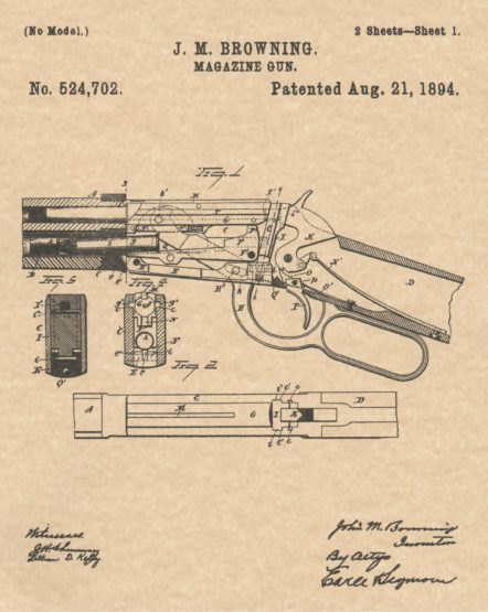 To all whom it may concern: Be it known that I, JOHN M. BROWNING, of Ogden, in the county of Weber and Territory of Utah, have invented a new. Improvement in Magazine Firearms; and I do hereby declare the following, when taken in connection With accompanying drawings and the letters and figures of reference marked thereon, to be a full, clear, and exact description of the same, and which said drawings constitute part of this specification, and represent, in—Figure 1, a broken view partly in section and partly in inside elevation of a magazine fire-arm constructed in accordance with my invention, and shown in its closed position; Fig. 2, a plan view of the arm; Fig. 3, a. view ‘Corresponding to Fig. 1, but showing the gun its open position; Fig. 4, a view in transverse section on the line of Fig. 1, looking rearward; Fig. 5, a view in transverse section on the line x–a; of Fig. 1, looking forward ; Fig. 6, a detached reverse plan view of the sliding breech block; Fig. 7, a detached plan view of the carrier; Fig. 8, a view thereof in transverse section on the line z—z of the preceding figure. My invention relates to an improvement in magazine firearms, the object being to produce a simple, compact, safe and reliable gun, in which the number of parts and the liability to derangement are reduced, which is constructed with particular reference to avoiding the choking of the gun by the incorrect presentation of a cartridge, or the failure of a cartridge to be properly handled by the breech mechanism, and which is designed to adapt the gun to take a longer cartridge than has heretofore been available for use in a similar gun having a receiver of the same .
With these ends in view, my invention con its in a magazine firearm having certain de, .tails of construction, as will be hereinafter described and pointed out in the claims. My improvements are applied to a gun having a barrel A, magazine B, receiver C, and stock D, all of approved construction, and not _needing special description or illustration. .In carrying out my invention, I employ an 5o, operating plate E, hung at its forward or muzzle end on a horizontal .pin E’, and moving up and down in a vertical plane on the said pin as a center. The extreme forward end of this plate is constructed with a lug or nose e, which rises, when the rear end of the plate is depressed, into the path taken by the cartridges 2, as they emerge from the magazine into the receiver, whereby the said lug or nose forms a magazine cutoff operating to prevent more than one cartridge from entering the receiver at a time. The said nose or lug rises into the path of the cartridges at the beginning of the opening movement of the gun,’ and is not retired or moved out of the said path until the min is again closed.
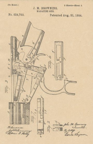 It insures the easy operation of the gun, as it prevents the head of the incoming. cartridge from resting upon or impinging against the forward end of the carrier F, and thus causing the same to work with difficulty. It also prevents the choking of the gun where the cartridges differ slightly in high, in which case, but for the said nose or lug, a short cartridge on the carrier might allow the next cartridge in the magazine to secure a partial entrance in to the receiver, and by fouling the action of the carrier, choke the gun. By the use of this lug or nose, I secure an effective magazine cutoff without complicating the gun by special independently organized devices for that purpose. The forward end of the operating plate E is also constructed with two lifting faces e’ e’, corresponding to each other, and respectively located below and on opposite sides of the nose e forming the magazine cut off. The extreme forward end of the carrier , rests upon the said lifting faces e’ e’ when the gun is closed, as shown in Fig. 1 of the drawings, the said. cud of the carrier being slotted or cut away to clear the magazine cut off lug e. At the beginning of the opening movement of the gun, the said lifting faces e’ e’ lift the carrier slightly, and hence the head of the cartridge, whereby the said head is brought into range with a .projection g, formed upon the under face of the forward end of the sliding breech bloc ) G, whereby the breechblock is caused to positively engage With the cartridge, and draw the same back into the receiver upon the carrier F, which is constructed as shown by Figs. 7 and 8 of the drawings, with a depression or pocket.