
Patent Description
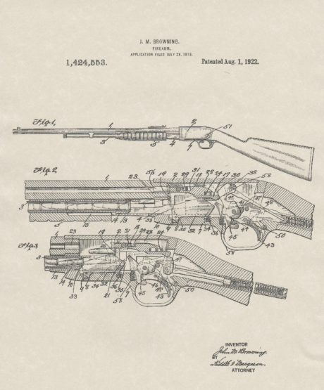
 To all whom it may concern: Be it known that I, JOHN M. BROWNING, of Ogden, in the county of Weber and State of Utah, have invented a new Improvement in Firearms; and I do hereby declare the following, when taken in connection with the accompanying drawings and the letters of reference marked thereon, to be full, clear, and exact description of the same, and which said drawings constitute part of this specification, and represent, in—Figure 1,a view in side elevation of the left hand side of an automatic firearm constructed in accordance with my invention; Fig. 2, a similar view of the right hand side thereof, showing the ejection opening formed in its receiver or gun frame; Fig. 3, a broken view, in vertical longitudinal section, showing the gun in the closed positions of its parts; Fig. 4, a less comprehensive broken view of the gun in vertical section drawn to full size and with the parts in their closed positions and with the trigger plate and all of its connected parts removed for the sake of clearness; Fig. 5,a detail section showing the breech bolt in its closed position, but with the locking block thereof in the unlocked position into which it is moved by the rocking tumbler.
Fig. 5°, a detached perspective view of the locking, block; Fig. 5°, a corresponding view of the operating tumbler thereof; Fig. 6, a broken view of the gun in vertical section, showing its parts in their open positions; Fig. 7, a detail view showing the co-action of the hammer with the two hooks constituting the double sea: of the trigger; Fig. 8, a corresponding but more comprehensive view showing the hammer, the trigger with its two books, and a safety catch which is here represented in its blocked or inoperative position; Fig. 9, a broken view of the gun in vertical section, showing the parts of the gun in the positions due to them when the gun has been opened manually instead of automatically. In this view the trigger plate, with its connected parts has been removed for the sake of clearness; Fig. 10, a broken view, in vertical section, of the receiver on the line a b of Fig. 2.
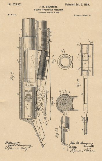
Fig. 11, a view in vertical section on the line e d of Fig. 9, looking rearward and taken through the gun barrel at a point close to the extension thereof; Fig. 12, a detached plan view of the breech bolt, showing the locking, block and rocking tumbler mounted therein ; Fig: 13, a broken view, in horizontal section, on the line of Fig. 2 and designed to show the carrier, the combined cartridge stop and carrier catch, and the sliding inertia piece or carrier catch lock; Fig. 14, a similar but less comprehensive view showing the carrier catch in the position which it has after it has been operated by a cartridge for releasing the carrier and is acting as a cartridge stop; Fig. 15, a detached plan view of the operating link and operating rod of the gun; Fig, 16, a detached view in longitudinal section of the link; Fig. 17, a detached broken view, in side elevation, of the carrier; Fig. 18, a detached plan view of the carrier; Fig. 19, a view of the rear of the carrier; Fig. 20, a detached reverse plan view of the breech bolt; Fig. 21, a detached view, in side elevation, of the sliding carrier catch lock or inertia piece; Fig. 22, a detached perspective view of the barrel extension.
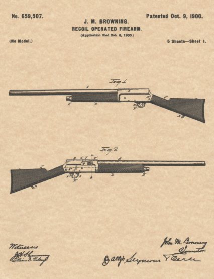
 My invention relates to an improvement in automatic portable firearms of the class in which the recoil following the explosion of a cartridge in the gun barrel is utilized to operate the breech mechanism of the gnu, the object of .my present invention being to produce an improved arm of this class in which the recoiling parts are housed for their protection, as well as the protection of the user of the arm, and in which the parts are constructed with particular reference to simplicity, of construction, strength, durability, and reliability of operation. With these ends in view my invention consists in certain details of construction and combinations of parts, as will be hereinafter described, and pointed out in the claims. In carrying out my invention as herein shown I provide a gun barrel A with a tube-like extension A’, into the forward end of which the barrel is screwed. This extension is located within and housed by the upper portion of the gun frame or receiver B, in which the extension reciprocates hack and forth, together with the barrel, the rear end of which centers the receiver during the recoil following the explosion of a cartridge in the barrel.