
Patent Description
 To all whom it may concern; Be it known that I, JOHN M. BROWNING, a citizen of the United States, residing in Ogden, in the county of Weber and State of Utah, have invented certain new and useful Improvements in Automatic. Firearms, of which the following is a specification, reference being had to the accompanying drawings, forming a part hereof. The invention relates to automatic firearms and more particularly to automatic firearms of the recoil operated type in which all the operations of the mechanism, except that of the trigger, are automatically effected. In my prior application for Letters Patent of the United States, Serial No. 680,963, filed December 15,.1923, for automatic firearms, there is shown and described an improved automatic of this character adapted to fire large caliber projectiles such as can be loaded with a high explosive charge, but so light in weight as to be mobile, adapted to be mounted on aircraft and fired from any position, and yet most durable. It is an object of the present invention to improve certain features of the automatic gun disclosed in said prior application and guns of similar character whereby said guns are rendered still more efficient and reliable in operation, simple in construction, and easier of manufacture.
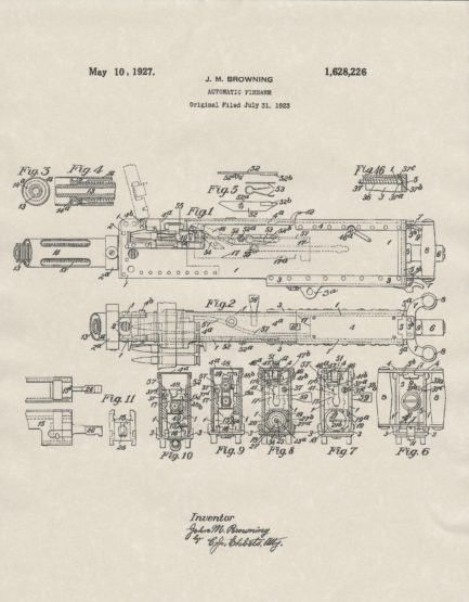
The improved features by which this object is attained comprise novel means for pushing the cartridges into the chamber of the barrel and for supporting and guiding said cartridges before and during such movement, novel means for extracting the empty shell and for steadying and guiding it during extraction, novel means for locking together the transversely movable breech locking and the longitudinally movable lock frame, novel means for readily positioning, supporting and guiding a transversely movable feeder carrying a plurality of cartridges for quick insertion into the transverse feed channel of the gun, and various other details of construction, and combinations and constructions of parts hereinafter more fully described and claimed. In the accompanying drawings : Fig. 1 represents a right hand side elevation of a gun in which. the novel, improved features of the invention are embodied. Fig. 2 represents a central, vertical, longitudinal section through the gun as seen from the right and on an enlarged scale; the barrel and barrel extension and the upper portion of the breech block are shown in section, while the lock frame and parts carried thereby are shown in elevation.
The front portion of the breech casing, and the greater portions of the barrel and of the recuperation have been broken away. Fig. 3 represents a partial central vertical longitudinal section through the .(run as seen from the left, the breech block being shown in its open position and the lock frame in its rearward position. Fig: 4 represents a vertical transverse section through the gun in the line 44 of Fig. 3 as seen from the rear ; the mechanism within the breech casing is shown in elevation and a portion of the breech block actuating is broken away. Fig. 5 represents a partial central vertical longitudinal section through the gun showing the parts of the mechanism at the instant when the lock frame is released and with a cartridge in position to be pushed into the barrel chamber. Fig. 6 represents a vertical transverse section through the gun in the line 66 of Fig. 5 as seen from the front, the carrier has been omitted and the cartridge about to be inserted into the barrel is shown in elevation. Fig. 7 represents the gun in a partial horizontal section through the axis of the barrel as seen from above and on an enlarged scale; a portion of the lock frame is broken away to show the mounting of the extractor and the extractor spring. A portion of the breech block is also broken away. Fig. 8 represents a partial vertical longitudinal section through the gun as seen from the right and on the same scale as Fig. 7, showing. the breech block and its actuating lever in an intermediate position during the manual opening.