Patent Description
To all whom it may concern: Be it known that I, JOHN M. BROWNING, residing at Ogden, in the county of Weber and State of Utah, have invented certain new and useful Improvements in Firearms, of which the following is a specification, reference being had to the accompanying drawings, forming a part hereof. This invention relates generally to automatic breech loading firearms, and more especially to firearms of this description in which the several operations—such as the opening of the breech after firing a shot, the ejection of the empty cartridge shell, the cocking of is the hammer, the presentation and introduction of a fresh cartridge into the chamber of the barrel, and the closing of the breech—are automatically effected by the pressure in the barrel of the gases generated by the explosion of the cartridge.
My invention comprises, further, improvements in firearms of the class described in United States Patent No. 580,926, applied for by me and granted April 20, 1897, said patent containing some of the features of the complete firearm which I have illustrated and described herein for the purpose of enabling my present invention to be understood. Such features as are common to the two constructions will be referred to herein so far as may be necessary to ‘enable the present invention to be understood; but the description which follows will relate particularly to the novel features of this case. The main object which I have had in view has been the production of a firearm of the class referred to which should be simple and inexpensive in construction, not liable to get out of order, and reliable and safe in operation under all conditions of use. I have hereinafter shown and described my present improvements as adapted to a gas operated magazine pistol; but I have chosen this particular kind of firearm merely as a convenient illustration of an embodiment of my invention and do not intend to restrict my invention to an application thereof to a magazine pistol nor to any particular kind of firearm, nor do I intend to restrict the invention to the use of the several features of improvement together in a common structure.
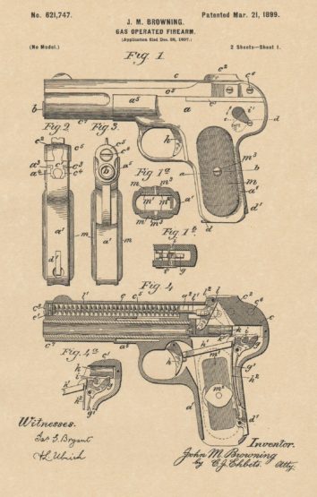
In the accompanying drawings, in which I have illustrated an embodiment of my invention, Figure 1 is a left hand side elevation of the pistol with the breech closed. Figs. 2 and 3 are respectively rear and front end views of the same. Fig. 4 is a longitudinal section, on a vertical plane, with the breech closed. Fig. 5 is a longitudinal section, on a vertical plane, with the breech open. Figs. 6, 7, 8, and 9 are detail views of parts to be referred to. Fig. l is a horizontal section on the plane indicated by the line a b of Fig. 1. Fig. 1b is a horizontal section on the plane indicated 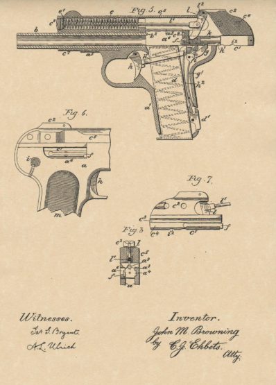 by the line c d of Fig. 1. The pistol represented in the accompanying drawings comprises a frame a, a barrel b, fixed in the frame, and a sliding breech piece c. The upper portion of the frame a forms the receiver and has a seat and suitable guides for the reciprocating breech piece, and below the receiver is the grip or handle a’, which is preferably made integral with the frame, but obviously may be formed separately and attached thereto in any suitable manner. Within the grip and extending through the same upward into the receiver is arranged a seat or chamber for the reception of the cartridge magazine d. The latter is substantially of ordinary form and construction and may consist of a sheet metal tube, in which the cartridges are laid one upon another, resting upon a spring follower, by which they are pushed upward into the receiver: It is conveniently retained in place within the grip by a spring actuated latch d’. Its upper end is open to permit the escape of the cartridges, the side walls at the rear of the opening being turned in to engage the rim or flange of the topmost cartridge and prevent the escape of the same from the holder except when it is pushed forward, as hereinafter described. The barrel b is secured to the receiver in any usual or suitable manner and extends forwardly from the same to the desired length. The upper portion of the frame is provided interiorly with longitudinal ribs and grooves as a4, Fig. 2, to engage corresponding ribs and grooves each of the breech piece c or of that portion of it which may be more properly coo designated as the ” breech bolt,” the said breech bolt or breech piece being thereby held to the frame and guided thereon in its reciprocation.
Patent Description
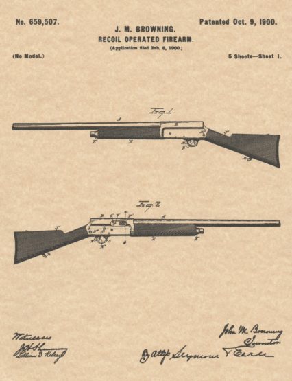
 To all whom it may concern: Be it known that I, John M. BROWNING, a citizen of the United States, residing at Ogden, in the county of Weber and State of Utah, have invented a new and useful Improvement in Firearms, of which the following is a specification, reference being had to the accompanying drawings, forming a part hereof. This invention relates to improvements in magazine firearms, and more especially to automatic firearms and particularly to automatic pistols in which energy is stored during the opening movement of the breech-slide in a spring, the reaction of which is utilized to actuate the return or closing movement of the breech-slide.
The main object of the invention is to produce a firearm of this class which shall be simple and inexpensive in construction, reliable, and safe under all conditions of use. Another object of the invention is to produce an automatic pistol specially adapted for accurate target practice, by haying the handle or grip of the pistol formed to be securely grasped and conveniently held in aiming and firing, and in which the frame of the arm shall support the comparatively long barrel rigidly, and in which the breech-slide may be at will and readily detached and removed from the frame, and be replaced and attached upon the same without requiring the use of any tool therefor. A further object of the invention is to provide the firearm with an automatic safety device for positively preventing the firing of the arm unless the breech is closed and all parts are in the proper firing position, and by the same device to always prevent 1 more than one shot from following upon each pull of the trigger.
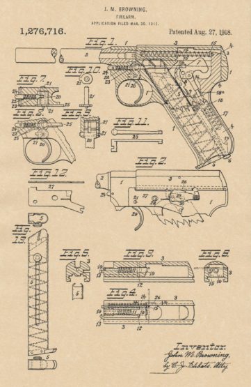
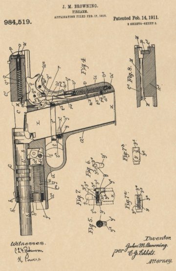
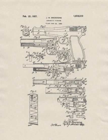
A further object is to provide the arm with a manual safety lock for at will and simultaneously locking the breech-slide and the cocked firing mechanism, and by this same device to provide the arm with a reliable indicator for showing at a. glance or touch whether the firing mechanism is in the cocked or in the released position. 1 These objects are attained by mechanism of simple and practical construction which is efficient, perfectly safe in use, and not liable to get out of order. The invention is shown herein as embodied in a gas-operated magazine pistol; but it will be understood that the invention is applicable to other firearms. In the accompanying drawings, wherein is illustrated an embodiment of the invention, Figure 1 is a left-hand side view of a central vertical section through the frame and the rear portion of the barrel with the breech closed and ready for firing; but showing the breech-slide in a vertical section in a plane somewhat to the left side of its central axis, thereby exposing to view the reaction spring and its guide for storing the energy of the recoil on firing a shot, and showing the manner in which the two ends of the reaction spring are supported, the front end in the breech-bolt and the rear end by the butt piece of the grip or mainspring housing. Fig. 2 is a left-hand side view of the upper portion of the frame of the pistol and of the breech-slide in the closed position. Fig. 3 is a central longitudinal section of the breech-slide, showing the firing pin with its retracting spring and locking pin in the breech-bolt.
Fig. 4 is a bottom view of the breech-slide. Fig. 5 is a vertical transverse section of the breech-bolt near its forward end looking forward, showing also an upper portion of the cartridge magazine. Fig. 6 is a vertical transverse section of the breech-slide in rear of the breech-bolt, indicating the respective positions of the firing pin and of the reaction spring and its guide rod, the spring and rod being shown in Figs. 4 and 6 as held in their forward compressed position by a transverse pin. Fig. 7 is a horizontal section through the forward portion of the frame below the barrel, showing a top view of the trigger and showing the trigger spring, its piston and its fastening plug. Fig. 8 is a partial vertical section of the frame showing the trigger in its place and above it the trigger spring, its piston and fastening plug. i Fig. 9 is a vertical transverse section of a portion of the frame, showing the hub and the pivot of the trigger, and the side plate, seen from the front. Fig. 10 shows the trigger pivot detached, in an end…view and in a top view. Fig. 11 Shows the trigger bar in a left hand side view and in an under side view.
Patent Description
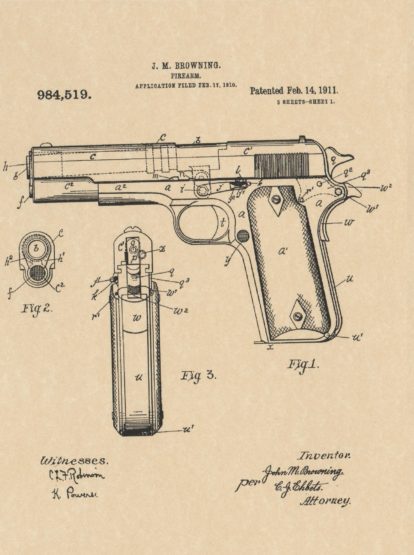 To all whom it may concern: Be it known that I, John M. BROWNING, citizen of the United States, residing in Ogden in the county of Weber and State of Utah have invented certain new and useful Improvements in Firearms, of which the following is a specification, reference being had to the accompanying drawings, forming a part hereof. The invention relates to automatic firearms of that description in which the several operations, as the opening of the breech after firing a shot, the ejection of the empty cartridge shell, the cocking of the hammer, is the presentation. and introduction of a loaded cartridge to the chamber of the barrel, and the closing and locking of the breech—are automatically effected through or by the energy of the recoil of the breech bolt or that part : which at the, time of firing the shot closes the breech of the barrel and the invention more especially relates to firearms of this description: winch, in firing, the barrel and the breech bolt are interlocked and recoil some distance together, and during this rearward movement the barrel has another movement imparted to it, Whereby it is unlocked from the breech bolt, and after its release the movements of the barrel are arrested, while the breech bolt continues to recoil until the breech is fully opened, and in which during the opening movement of the breech bolt energy is stored in a spring, the reaction of which is utilized to effect the return or closing movement of the breech bolt.
It is essential for the proper operation of firearms of this class that the breech bolt and the parts connected and moving with it should be made as heavy as practicable, so that it may store a maximum amount of energy in the short time during which on firing the rearward pressure of the powder gases in the barrel acts upon the breech bolt and initiates its recoil, mind so that the breech bolt nifty continue to recoil under its momentum alone to complete the opening of the breech and the compression of the reaction spring after the gas pressure has ceased because relieved by the exit of the bullet from the barrel. On account of the limited total weight practical for a small arm, and especially for a pistol, it is necessary in order to be able to give a maximum weight to the breech bolt, that the other parts of the, arm, the frame and the barrel, be constructed as light as possible.
 This is especially important regarding the barrel of this class of arms, for the additional reason that at the commencing of the recoil the light barrel may readily yield to and move rear ward with the breech bolt while it remains interlocked therewith, and in order that when unlocked from the breech bolt, the movements of the barrel may be arrested, without causing by this sudden stopping in. jury to either the barrel or the frame of the arm. The main object of the present invention is to produce a firearm of this class which, in order to be specially adapted for the tary service, I be not only practical, efficient and perfectly safe in use, but strong and capable of withstanding the exposure and rough usage of service in the field and adapted to fire cartridges having bullets of large caliber and weight and powerful charges of powder; it shall also be very Simple in construction so as to be reliable under all conditions of service and not liable to get Out of order, inexpensive of manufacture, with a minimum number of parts; and readily dismounted and cleaned without requiring the use of any tools.
Another object of the invention is to produce a firearm of this .class in which to in sure the absolute safety of the user. the breech slide, comprising the breech bolt and the forward extension of the same covering the barrel, and the movable abutment enclosing the reaction spring shall be combined in one strong integral whole without a division or joint therein and shall be mounted upon the top of the frame from the front, to be so held and guided in its reciprocation thereon that it can be removed from the frame as one whole only and in the forward direction alone, by which the possibility of any part of the arm being thrown rearward shall be positively guarded against. Another object of the invention is to produce a firearm of this class in which the barrel shall first be seated ‘in the forward part of the breech slide, shall then be mounted with the breech slide upon the frame from ..the front, and finally the barrel shall be securely connected with and movably attached to the frame in ‘such a manner that the barrel may be at will and readily detached and disconnected from the frame, so that it can be removed from the frame with the breech slide in the forward direction only.
Patent Description
 To all whom it may concern: Be it known that I, JOHN M. BROWNING, a citizen of the United States, residing in Ogden, in the county of Weber and State of Utah, have invented certain new and useful Improvements in Safety Devices for Firearms, of which the following is a specification, reference being had to the accompanying drawings, forming a part hereof. The invention relates to safety devices for breech loading firearms generally, and it is more especially applicable to automatic firearms in which the .several operations—such as the opening of the breech after firing a shot, the ejection of the empty cartridge shell, the cocking of the hammer, the presentation and introduction of a loaded cartridge into the chamber of the barrel, and the closing of the breech—are automatically effected by the pressure in the barrel of the powder gases generated by the explosion of the cartridge.
The main object of the invention is to provide for the firearms of this class, in which for safety in handling and carrying the members of the firing mechanism, with the exception of the trigger, are entirely enclosed and concealed in the arm, a safety device for at will and readily locking the breech mechanism in its closed forward position, and at the same time positively locking the concealed firing mechanism when cocked; or for at will and as readily unlocking these parts, and thereby adapting the arm for instant use. For safety and convenience, while examining and cleaning the arm and while charging it with cartridges, said safety device shall, further, be adapted for at will locking the breech mechanism in its open rearward position; or for as readily unlocking said mechanism and allowing the same to close. Another object of the invention is to produce a safety device which shall be simple and inexpensive in construction, strong, reliable and safe under all conditions of use. These objects are attained by mechanism of simple and practical construction, which is efficient, perfectly safe in use and not 1 liable to get out of order. The invention is shown herein as embodied in a gas operated magazine pistol, but it will be understood that the invention is applicable to other firearms.
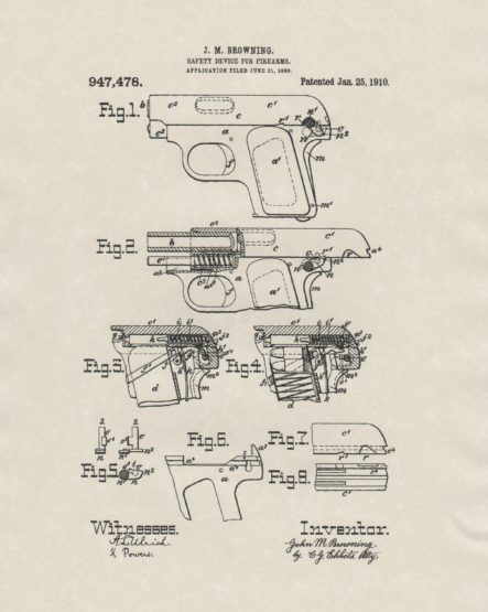
Therefore it is not intended to restrict the present invention to. a. magazine pistol, nor to any particular kind of firearm. In the accompanying drawings, wherein is illustrated an embodiment of the invention, Figure 1 is a left hand side elevation of the pistol with the breech closed, and with the safety device turned to the operative locking position; the non-operative unlocked position of the same being indicated in dotted lines. Fig. 2 is an elevation similar to Fig. 1, but partly in section and with the breech open, and with the safety device turned to lock the breech slide in the open rear position. Fig. 3 is a longitudinal section of the upper rear portion of the pistol, with the breech closed and the firing mechanism cocked and locked by the safety device. Fig. 4 is a section similar to Fig. 3, but with the safety device turned to unlock the breech slide and the firing mechanism. Fig. 5 shows detail views of the safety locking lever detached, respectively at 1 a side elevation, at 2 a top view, and at 3 a front view. Fig. 6 is a side elevation of the upper rear portion of the frame’ of the pistol detached, with the breech slide and other mechanisms removed.
Fig. 7 is, a side view of the rear portion of the breech slide detached. Fig. 8 is a bottom view of the rear portion of the breech slide detached. Similar letters refer to similar parts throughout the several views. In the pistol represented in the drawings a is the frame, 7, the barrel, and c the breech slide. The top of the frame a, upon the I forward portion of which the barrel b is mounted, forms the seat for the reciprocating breech slide c. In rear of the barrel b, the upper portion of the frame forms the receiver and below it is the grip or handle al, preferably made integral with the frame, and the hollow inside’ of which forms the seat for the reception of the cartridge magazine d, which is a tube holding a number of cartridges one upon the other resting upon a spring pressed follower, the magazine is inserted into the grip from below, so that its top communicates with the receiver and with the rear of the barrel, and at each opening.
Patent Description
 My invention relates to automatic firearms of that description in which all operations of the mechanism, except that of the trigger, are automatically effected by the energy of recoil of movable parts. A main object of the present invention is to provide an automatic pistol of this character which is strong, simple in construction, accurate, reliable and safe in operation, and easy and economical of manufacture. This object is attained by . simplifying the mechanism employed in firearms of this class by providing a novel improved construction and coordination of certain members of the. mechanism, thereby enabling these parts to perform several distinct functions and thus reducing the .number of component parts and by giving to all parts such form and organizing them in such manner that they may be readily assembled or disassembled without requiring the use of any tools or accessories.
Other and further objects and advantages of my new improvements will appear from the specifications and drawings in which I show and describe an automatic pistol incorporating my improvements in a preferred form. Also the utility and value of some of my improvements are. not limited to their use in an automatic pistol but they are equally valuable and useful in any automatic firearm of the recoil operated type. in the accompanying drawings: Fin. I is a front view of the forward portion of the frame, the breech slide and the barrel of a pistol embodying my new improvements. Fig. 2 is a left hand side elevation of said Fig. 3 is a central vertical longitudinal section through the forward portion of the arm, showing the barrel and breech slide in their forward locked position, and the trio. trey in its normal position. Certain of the parts are shown in elevation. Fig. 4 shows the trigger and the parts mounted thereon detached, in a front view and in a left hand side view; in the side view, the rear portion of the trigger is shown in a vertical longitudinal section. Fig. 5 is a central vertical longitudinal section of a portion of the frame, including the trigger, showing the trigger elevation and in position for bodily down ward movement to withdraw it from its seat in the frame, the barrel having been removed from the frame.
Fig. 6 is a central vertical longitudinal section through the upper portion of the arm, showing the barrel and breech slide in their rearward positions, and the trigger in its normal position. Certain of the parts are shown in elevation. Fig. 7 is R. bottom view of the breech slide with the breech bolt in place in the rear portion of said slide. Fig. 8 is a. top view of the frame, showing the cartridge magazine, having a cartridge remaining therein, in. its seat in the frame and Mao showing the slide stop in its relation to the magazine follower. :Fig. 0 is a central vertical longitudinal section through a portion of the arm, showing the movable parts in the position they occupy at the instant when a shell is being ejected; in this view the forward portion of the breech bolt is vertically sectioned in the plane of the ejector and the ejector with the part of the frame with which it is integrally formed are shown in elevation. Fig. 10 shows the ejector and the part of the frame with which it is integrally formed, detached, in a top view, in a left hand side view and in a front view. Fig. 11 is a left hand side view of the E magazine detached.
Fig. 12 is a central vertical longitudinal section through the upper rear portion of the arm, showing? the barrel, breech slide and breech bolt in their forward position and the firing pin in the unlocked position, certain of the parts being shown in elevation. Fig. 13 is a central vertical longitudinal section through the upper rear portion of the arm, showing the breech slide and breech bolt some distance rearward of their forward. position and the firing .pin and sear in the cocked .position. Certain of the parts are shown in elevation. Fig. 14 is a central vertical longitudinal section through the upper rear portion of the frame, as seen from the right, showing the breech bolt. in its forward position and showing also the connections between the trigger and the sear. Certain parts are shown in elevation.
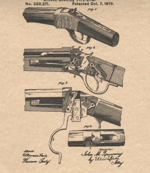
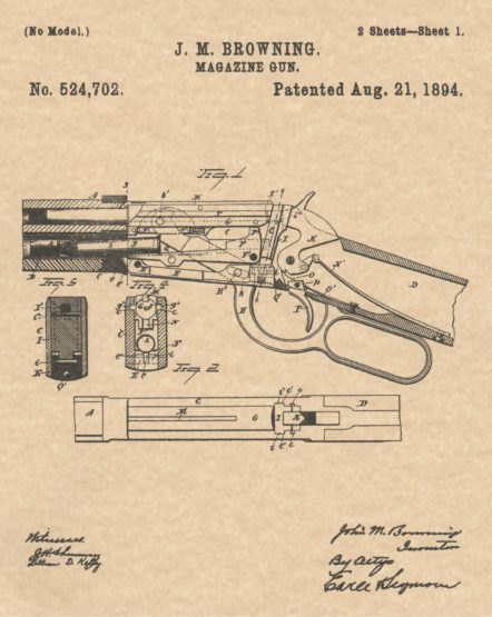 To all whom it may concern: Be it known that I, JOHN M. BROWNING, of Ogden, in the county of Weber and Territory of Utah, have invented a new. Improvement in Magazine Firearms; and I do hereby declare the following, when taken in connection With accompanying drawings and the letters and figures of reference marked thereon, to be a full, clear, and exact description of the same, and which said drawings constitute part of this specification, and represent, in—Figure 1, a broken view partly in section and partly in inside elevation of a magazine fire-arm constructed in accordance with my invention, and shown in its closed position; Fig. 2, a plan view of the arm; Fig. 3, a. view ‘Corresponding to Fig. 1, but showing the gun its open position; Fig. 4, a view in transverse section on the line of Fig. 1, looking rearward; Fig. 5, a view in transverse section on the line x–a; of Fig. 1, looking forward ; Fig. 6, a detached reverse plan view of the sliding breech block; Fig. 7, a detached plan view of the carrier; Fig. 8, a view thereof in transverse section on the line z—z of the preceding figure. My invention relates to an improvement in magazine firearms, the object being to produce a simple, compact, safe and reliable gun, in which the number of parts and the liability to derangement are reduced, which is constructed with particular reference to avoiding the choking of the gun by the incorrect presentation of a cartridge, or the failure of a cartridge to be properly handled by the breech mechanism, and which is designed to adapt the gun to take a longer cartridge than has heretofore been available for use in a similar gun having a receiver of the same .
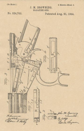 It insures the easy operation of the gun, as it prevents the head of the incoming. cartridge from resting upon or impinging against the forward end of the carrier F, and thus causing the same to work with difficulty. It also prevents the choking of the gun where the cartridges differ slightly in high, in which case, but for the said nose or lug, a short cartridge on the carrier might allow the next cartridge in the magazine to secure a partial entrance in to the receiver, and by fouling the action of the carrier, choke the gun. By the use of this lug or nose, I secure an effective magazine cutoff without complicating the gun by special independently organized devices for that purpose. The forward end of the operating plate E is also constructed with two lifting faces e’ e’, corresponding to each other, and respectively located below and on opposite sides of the nose e forming the magazine cut off. The extreme forward end of the carrier , rests upon the said lifting faces e’ e’ when the gun is closed, as shown in Fig. 1 of the drawings, the said. cud of the carrier being slotted or cut away to clear the magazine cut off lug e. At the beginning of the opening movement of the gun, the said lifting faces e’ e’ lift the carrier slightly, and hence the head of the cartridge, whereby the said head is brought into range with a .projection g, formed upon the under face of the forward end of the sliding breech bloc ) G, whereby the breechblock is caused to positively engage With the cartridge, and draw the same back into the receiver upon the carrier F, which is constructed as shown by Figs. 7 and 8 of the drawings, with a depression or pocket.
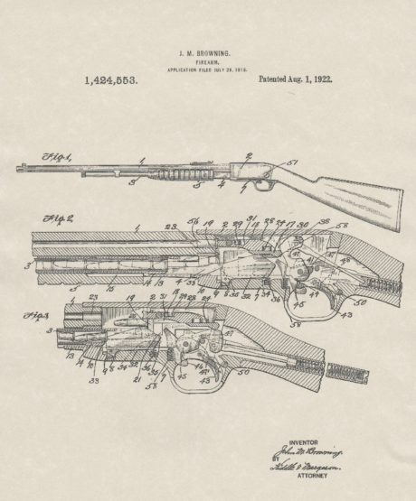
 To all whom it may concern: Be it known that I, JOHN M. BROWNING, of Ogden, in the county of Weber and State of Utah, have invented a new Improvement in Firearms; and I do hereby declare the following, when taken in connection with the accompanying drawings and the letters of reference marked thereon, to be full, clear, and exact description of the same, and which said drawings constitute part of this specification, and represent, in—Figure 1,a view in side elevation of the left hand side of an automatic firearm constructed in accordance with my invention; Fig. 2, a similar view of the right hand side thereof, showing the ejection opening formed in its receiver or gun frame; Fig. 3, a broken view, in vertical longitudinal section, showing the gun in the closed positions of its parts; Fig. 4, a less comprehensive broken view of the gun in vertical section drawn to full size and with the parts in their closed positions and with the trigger plate and all of its connected parts removed for the sake of clearness; Fig. 5,a detail section showing the breech bolt in its closed position, but with the locking block thereof in the unlocked position into which it is moved by the rocking tumbler.
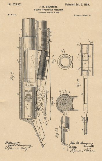 My invention relates to an improvement in automatic portable firearms of the class in which the recoil following the explosion of a cartridge in the gun barrel is utilized to operate the breech mechanism of the gnu, the object of .my present invention being to produce an improved arm of this class in which the recoiling parts are housed for their protection, as well as the protection of the user of the arm, and in which the parts are constructed with particular reference to simplicity, of construction, strength, durability, and reliability of operation. With these ends in view my invention consists in certain details of construction and combinations of parts, as will be hereinafter described, and pointed out in the claims. In carrying out my invention as herein shown I provide a gun barrel A with a tube-like extension A’, into the forward end of which the barrel is screwed. This extension is located within and housed by the upper portion of the gun frame or receiver B, in which the extension reciprocates hack and forth, together with the barrel, the rear end of which centers the receiver during the recoil following the explosion of a cartridge in the barrel.
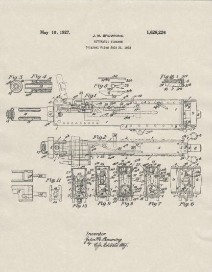
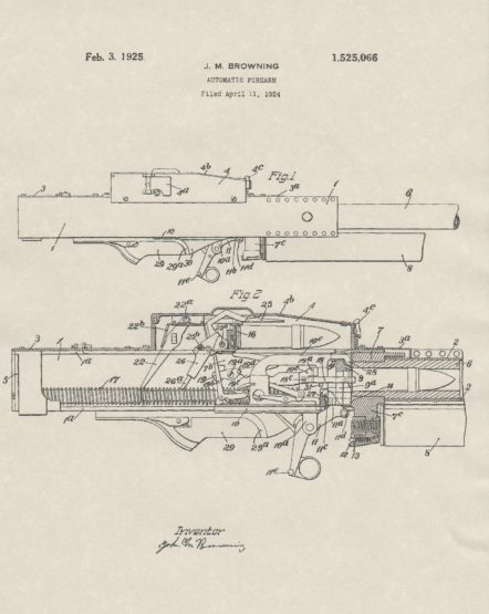 To all whom it may concern; Be it known that I, JOHN M. BROWNING, a citizen of the United States, residing in Ogden, in the county of Weber and State of Utah, have invented certain new and useful Improvements in Automatic. Firearms, of which the following is a specification, reference being had to the accompanying drawings, forming a part hereof. The invention relates to automatic firearms and more particularly to automatic firearms of the recoil operated type in which all the operations of the mechanism, except that of the trigger, are automatically effected. In my prior application for Letters Patent of the United States, Serial No. 680,963, filed December 15,.1923, for automatic firearms, there is shown and described an improved automatic of this character adapted to fire large caliber projectiles such as can be loaded with a high explosive charge, but so light in weight as to be mobile, adapted to be mounted on aircraft and fired from any position, and yet most durable. It is an object of the present invention to improve certain features of the automatic gun disclosed in said prior application and guns of similar character whereby said guns are rendered still more efficient and reliable in operation, simple in construction, and easier of manufacture.